Electronic Data Systems
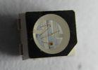
1.10mm Height 1210 Full - Color bright smd rgb led 3.5x2.8x1.9mm customized
DL-PCB1210RGBC
Description
1.10mm Height 1210 Full - Color bright smd rgb led 3.5x2.8x1.9mm customized
?
1. More than 10 years experience in LED industrial.
2. Biggest LED manufacturer by shipment in China,Asia.
3. Have cooperated with such big companies as Samsung,Xiaomi,etc.
4. High quality compliance with the international standard,pass CE, FCC, REACH, RoHS, UL.
5. The most important thing is that our price is more competitive with our high quality.
?
Package Dimension:
?
- - - -
Part No. | Chip Material | Lens Color | Source Color |
DL-PCB1210RGBC | InGaN | Water Clear | RGB |
- - - -
?
?
?
?
?
?
# ?
# Applications:
# Automotive: Backlight in dashboards and switches.
# Telecommunication: Indicator and backlight in telephone and fax.
# Indicator and backlight for audio and video equipment.
# Indicator and backlight in office and family equipment.
# Flat backlight for LCD’s, switches and symbols.
# Light pipe application.
# General use.
# Absolute Maximum Ratings at Ta=25℃
#
- - - -
Parameters | Symbol | MAX | Unit |
Power Dissipation | PD | Hyper Red | 60 | mW |
Pure Green | 95 |
Blue | 95 |
Peak Forward Current (1/10 Duty Cycle, 0.1ms Pulse Width) | IFP | Hyper Red | 100 | mA |
Pure Green | 100 |
Blue | 100 |
Continuous Forward Current | IF | Hyper Red | 25 | mA |
Pure Green | 25 |
Blue | 25 |
Reverse Voltage | VR | 5 | V |
Electrostatic Discharge (HBM) | ESD | Hyper Red | 2000 | V |
Pure Green | 1000 |
Blue | 1000 |
Operating Temperature Range | Topr | -40℃ to +85℃ |
Storage Temperature Range | Tstg | -40℃ to +100℃ |
Soldering Temperature | Tsld | 260℃ for 5 Seconds |
- - - -
?
?
?
?
Electrical Optical Characteristics at Ta=25℃
- - - -
Parameters | Symbol | Emitting Color | Min. | Typ. | Max. | Unit | Test Condition |
Luminous Intensity | IV | Hyper Red | 120 | 180 | --- | mcd | IF=20mA (Note 1) |
Pure Green | 300 | 500 | --- |
Blue | 80 | 140 | --- |
Viewing Angle | 2θ1/2 | Hyper Red | --- | 120 | --- | Deg | IF=20mA (Note 2) |
Pure Green | --- | 120 | --- |
Blue | --- | 120 | --- |
Peak Emission Wavelength | λp | Hyper Red | --- | 632 | --- | nm | IF=20mA (Measurement @Peak) |
Pure Green | --- | 520 | --- |
Blue | --- | 468 | --- |
Dominant Wavelength | λd | Hyper Red | --- | 624 | --- | nm | IF=20mA (Note 3) |
pure Green | --- | 525 | --- |
Blue | --- | 470 | --- |
Spectral Line Half-Width | △λ | Hyper Red | --- | 20 | --- | nm | IF=20mA |
Pure Green | --- | 35 | --- |
Blue | --- | 25 | --- |
Forward Voltage | VF | Hyper Red | 1.80 | 2.20 | 2.40 | V | IF=20mA |
Pure Green | 3.00 | 3.30 | 3.80 |
Blue | 3.00 | 3.30 | 3.80 |
Reverse Current | IR | Hyper Red | --- | --- | 10 | μA | VR=5V |
Pure Green | 50 |
Blue | 50 |
- - - -
?
Notes:
# Luminous intensity is measured with a light sensor and filter combination that approximates the CIE eye-response curve.
# θ1/2 is the off-axis angle at which the luminous intensity is half the axial luminous intensity.
# The dominant wavelength (λd) is derived from the CIE chromaticity diagram and represents the single wavelength which defines the color of the device.
# Package Dimension:
# Reliability Test Items And Conditions (Per Chip):
#
The reliability of products shall be satisfied with items listed below:
Confidence level: 90%.
LTPD: 10%.
1) Test Items and Results:
- - - -
No. | Test Item | Test Hours/Cycles | Test Conditions | Sample Size | Ac/Re |
1 | Resistance to Soldering Heat | 6 Min | Tsld=260±5℃, Min. 5sec | 25pcs | 0/1 |
2 | Thermal Shock | 300 Cycles | H: +100℃ 5min ∫ 10 sec L: -10℃ 5min | 25pcs | 0/1 |
3 | Temperature Cycle | 300 Cycles | H: +100℃ 15min ∫ 5min L: -40℃ 15min | 25pcs | 0/1 |
4 | High Temperature Storage | 1000Hrs. | Temp: 100℃ | 25pcs | 0/1 |
5 | DC Operating Life | 1000Hrs. | IF=20mA | 25pcs | 0/1 |
6 | Low Temperature Storage | 1000Hrs. | Temp: -40℃ | 25pcs | 0/1 |
7 | High Temperature/ High Humidity | 1000Hrs. | 85℃/85%RH | 25pcs | 0/1 |
- - - -
?
2) Criteria for Judging the Damage:
- - - -
Item | Symbol | Test Conditions | Criteria for Judgment |
Min | Max |
Forward Voltage | VF | IF=20mA | --- | F.V.*)×1.1 |
Reverse Current | IR | VR=5V | --- | F.V.*)×2.0 |
Luminous Intensity | IV | IF=20mA | F.V.*)×0.7 | --- |
- - - -
?
?
# Features:
# Package in 8mm tape on 7” diameter reel.
# Compatible with automatic placement equipment.
# Compatible with infrared and vapor phase reflow solder process.
# Full-Color Type.
# The product itself will remain within RoHS compliant Version.
?
# Descriptions:
# The PCB1210 SMD LED is much smaller than lead frame type components, thus enable smaller board size, higher packing density, reduced storage space and finally smaller equipment to be obtained.
# Besides, lightweight makes them ideal for miniature applications .etc.
?
# Applications:
# Automotive: Backlighting in dashboard and switch.
# Telecommunication: Indicator and backlighting in telephone and fax.
# Flat backlight for LCD, switch and symbol.
# Indoor signboard use.
# General use
# Absolute Maximum Ratings at Ta=25℃
- - - -
Parameters | Symbol | Emitting Color | Max. | Unit |
Power Dissipation | PD | Hyper Red | 60 | mW |
Pure Green | 95 |
Blue | 95 |
Peak Forward Current (1/10 Duty Cycle, 0.1ms Pulse Width) | IFP | Hyper Red | 100 | mA |
Pure Green | 100 |
Blue | 100 |
Continuous Forward Current | IF | Hyper Red | 25 | mA |
Pure Green | 25 |
Blue | 25 |
Reverse Voltage | VR | 5 | V |
Electrostatic Discharge (HBM) | ESD | Hyper Red | 2000 | V |
Pure Green | 400 |
Blue | 400 |
Operating Temperature Range | Topr | -40℃ to +80℃ |
Storage Temperature Range | Tstg | -40℃ to +85℃ |
Soldering Temperature | Tsld | 260℃ for 5 Seconds |
- - - -
?
?
?
?
?
?
?
?
?
?
?
?
Electrical Optical Characteristics at Ta=25℃
- - - -
Parameters | Symbol | Emitting Color | Min. | Typ. | Max. | Unit | Test Condition |
Luminous Intensity | IV | Hyper Red | 50 | 70 | --- | mcd | IF=20mA (Note 1) |
Pure Green | 225 | 260 | --- |
Blue | 60 | 100 | --- |
Viewing Angle | 2θ1/2 | Hyper Red | --- | 120 | --- | Deg | IF=20mA (Note 2) |
Pure Green | --- | 120 | --- |
Blue | --- | 120 | --- |
Peak Emission Wavelength | λp | Hyper Red | --- | 632 | --- | nm | IF=20mA |
Pure Green | --- | 520 | --- |
Blue | --- | 468 | --- |
Dominant Wavelength | λd | Hyper Red | --- | 624 | --- | nm | IF=20mA (Note 3) |
Pure Green | --- | 525 | --- |
Blue | --- | 470 | --- |
Spectral Line Half-Width | △λ | Hyper Red | --- | 20 | --- | nm | IF=20mA |
Pure Green | --- | 35 | --- |
Blue | --- | 25 | --- |
Forward Voltage | VF | Hyper Red | 1.60 | 2.00 | 2.40 | V | IF=20mA |
Pure Green | 2.80 | 3.40 | 3.80 |
Blue | 2.80 | 3.40 | 3.80 |
Reverse Current | IR | Hyper Red | --- | --- | 10 | μA | VR=5V |
Pure Green | 50 |
Blue | 50 |
- - - -
?
# Reliability Test Items And Conditions:
The reliability of products shall be satisfied with items listed below:
Confidence level: 90%.
LTPD: 10%.
1) Test Items and Results:
- - - -
No. | Test Item | Test Hours/Cycles | Test Conditions | Sample Size | Ac/Re |
1 | Resistance to Soldering Heat | 6 Min | Tsld=260±5℃, Min. 5sec | 25pcs | 0/1 |
2 | Thermal Shock | 300 Cycles | H: +100℃ 5min ∫ 10 sec L: -10℃ 5min | 25pcs | 0/1 |
3 | Temperature Cycle | 300 Cycles | H: +100℃ 15min ∫ 5min L: -40℃ 15min | 25pcs | 0/1 |
4 | High Temperature Storage | 1000Hrs. | Temp: 100℃ | 25pcs | 0/1 |
5 | DC Operating Life | 1000Hrs. | IF=20mA | 25pcs | 0/1 |
6 | Low Temperature Storage | 1000Hrs. | Temp: -40℃ | 25pcs | 0/1 |
7 | High Temperature/ High Humidity | 1000Hrs. | 85℃/85%RH | 25pcs | 0/1 |
- - - -
?
2) Criteria for Judging the Damage:
- - - -
Item | Symbol | Test Conditions | Criteria for Judgment |
Min | Max |
Forward Voltage | VF | IF=20mA | --- | F.V.*)×1.1 |
Reverse Current | IR | VR=5V | --- | F.V.*)×2.0 |
Luminous Intensity | IV | IF=20mA | F.V.*)×0.7 | --- |
- - - -
# Package Dimension:
# Reel Dimensions
#
Carrier Tape Dimensions
Loaded quantity 2000PCS per reel.
Notes:
# Luminous Intensity Measurement allowance is ± 10%.
# θ1/2 is the off-axis angle at which the luminous intensity is half the axial luminous intensity.
# The dominant wavelength (λd) is derived from the CIE chromaticity diagram and represents the single wavelength which defines the color of the device.
?
?
# # Luminous intensity is measured with a light sensor and filter combination that approximates the CIE eye-response curve.
# θ1/2 is the off-axis angle at which the luminous intensity is half the axial luminous intensity.
# The dominant wavelength (λd) is derived from the CIE chromaticity diagram and represents the single wavelength which defines the color of the device.
?
?
?
?
?
Read More
HongKong Double Light Electronics Technology Company
LED Light Components,Indicator LED,Infrared Emitting Diode
Address: 7-G,Duhui 100 building,No.4 Zhonghang Road,Futian District,Shenzhen City, Guangdong Province China,Zip:518000,
Shenzhen, Guangdong
China, 518000
Tel: 86-755-82853859
Fax: 86-755-83229774
